Just Another Beep-Boop Machine
Just Another Beep-Boop Machine is a small artwork, made to create an opportunity to play with music. A participant can punch holes in the provided cards, which are then used as the input information for the device to play a tune.
The Just Another Beep-Boop Machine is a small artwork, made to create an opportunity to play with music. A participant can punch holes in the provided cards, which are then used as the input information for the device to play a tune, as can be seen in the video above. The cards can be used to reproduce familiar songs, or to just punch as many holes as you can, to see what happens.
How it works
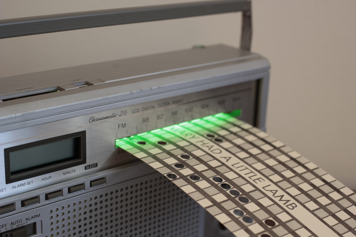
The glowing green light emanating from the mouth of the device is actually a key part of its function: the holes punched into the cards allow the light to hit a corresponding sensor, which signals the microcontroller to play the requisite note. When the card is inserted, it covers the center light sensor, triggering the movement of the servo which draws in the card to play the song.
Its guts kind of look like this:
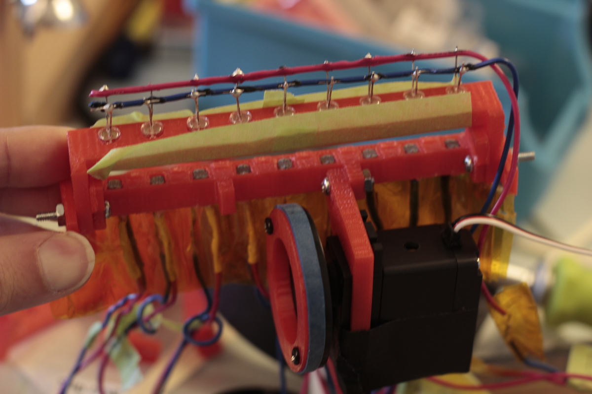
There you can see the array of LEDs, and photo-resisters which activate the sound. Not pictured is the microcontroller brain, which for this project was an Espruino Pico, flashed with MicroyPython (a process I detail here).
How To
I can not promise that this will be a comprehensive guide, but it should be a good foundation for you to try a similar project.
First some preliminary steps:
- Grab all of the project's 3D models and assets from Thingiverse (don't forget to download the card templates from here as well!)
- Get the source code for the project here
- Review how to wire up a photo-resistor to a micocontroller from this post (though that code example is for an Arduino)
The 3D model file LED-holder.stl is the top mount for the LEDs, and will need to be 3D printed. For this project I used something similar to these (which were actually just a bit too bright). The LEDs just need to be mounted into this holder, and then wired in series to the microcontroller.
The file sensor-holder.stl, as you can guess, will hold the light sensors. Each needs to be mounted, and then wired to a specific pin on your microcontroller. For this project, the sensors are being used as a simple on-off switch, instead of sending analogue information. This makes the project a bit more flexible, as it does not require a crazy amount of analogue pins. The sensor-holder.stl and LED-holder.stl need to be connected with a 4-40 bolt on each side.
The servo is held in place by servo-mount-no-holes.stl, but the 3D-printable file does not have holes to bolt the servo in place, and so those will have to be drilled in later (...or you can just affix the servo to the mount with some tape, while you are adjusting its placement). The exact servo I used was this one, but just about any continuous rotation servo of a similar size should work. Once in place, attach the ring.stl to a servo disc, and then slide on an elastic band for some grip. The one sort of tricky thing is that you will have to find a way to put some pressure on the wheel, in order to drive the card through.
The Code
As mentioned above, the code runs on a microcontroller running MicroPython, and the script can be found here. You just need to wire up the components to the pins outlined in the code (or equivalent for different boards), and upload the main.py onto your device.
Really though, this project can be done on almost any microcontroller, as long as you write a script with similar logic. Basically, the main.py script just does this:
- Initialize the pins corresponding to the light sensors as inputs.
- Set up a PWM pin to output to a speaker or piezo buzzer.
- Create a function which takes the pin receiving light, and then activates the piezo to play the corresponding note.
- Wrap this all up in a loop that checks to see which pins are full of light, and then act accordingly.